Garrett GTI 2500 Hip Mount Modifications
By Mitch King
Updated February 2010
To check back for any updates that I might posted.
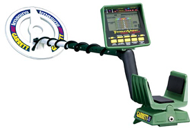
This page will be dedicated to converting a Garrett GTI2500 to a hip mount configuration.
Remember performing this modification will null any warranties you have on your machine.
This modification is not sanctioned by Garrett Electronics.
I have used a GTI-1500 for many years, almost since it was introduced. But for a Civil War relic hunting I felt I need a true all metal mode that the 1500 does not have. That's why I picked up a GTI-2500. But the 1st thing I noticed was how much more heavier this unit was compared to my 1500. At almost a 1/2 pound more, that can really get heavy after 6 to 10 hours of swinging. That's when I decided to investigate the possibility of a chest or hip mount conversion. The batteries and speaker are already hip mountable. But using that configuration made the unit VERY unbalanced. I first checked the net and found no references to such a conversion on the 1500 or the 2500. The only thing I did find was individuals wanting the same thing I did. This proved to be a mechanical and technical challenge. First off the control housing is an integral part of the main shaft and the design is based on balance. Next the coil cable was to short to connect the the electronics and still be able to swing the shaft and coil. So two major things had to be addressed first. I had to make an extension cable for the coil and battery box. Second I had to make a bracket to hold the main electronics in a usable manner. One of the best things about this modification is it IS NOT permanent. The unit can be re-assembled to the factory configuration. There is NO soldering done to the detector electronics. This mod can also be used on the GTI-1500.
I will provide diagrams and pictures here to help in the modification. Read this page several times and review it carefully before attempting these modifications.
I am an electronics technician with over 30 years of experience. This was a simple task for me, but might be above the average persons capabilities.
Before starting this project, Remove the batteries from the unit first !!
 |
 |
 |
 |
 |
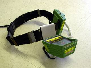 |
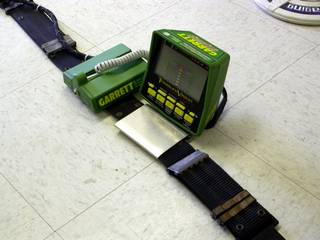
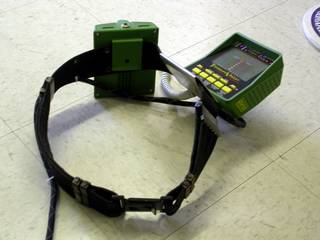
The above pictures are how my assembly turned out.
I have broken the modifications down to 5 sections.
1. Building the coil extension cable.
2. Obtaining the correct battery/speaker box replacement cable.
3. Constructing the hip mount bracket.
4. Disassembling unit.
5. Reassembling the unit with the modifications.
1. Building the coil extension cable.

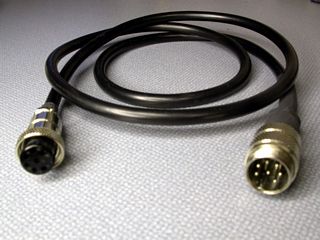
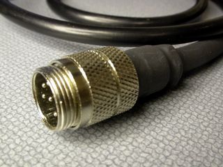
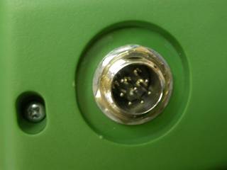
This is the only part of this modification that requires soldering. These connectors are small a require some level of skill to solder on and assemble. The first picture is an extension cable I made by using 2 new connectors and separate wires in a sheath. I did not have the signal pairs shielded correctly and was prone to noise and interference. The second picture is a better assembly using an old GTI coil cable. Try to obtain a non working coil. It must be for the GTI series of detectors (7 pin connector). I cut the coil from the cable leaving it as long as possible. I then added the male 7 pin male connector (3rd picture). This cable is 1 to 1, meaning pin 1 on the male side is connected to pin 1 of the female side. Same with pin 2 and so forth. I will provide a schematic of the cable here soon. You can disassemble the existing connector and see how the cable is made. Pay attention to the shielding. To open the connector, start by removing the two clamp screws at the rear of the connector. Then there is a very small set screw near the front, under the locking ring. This screw is very small, don't loose it. The plastic part with the pins is a twist locked into the metal housing. Re-assemble in the reverse order. Once complete, you can use an volt/ohm meter to "beep out" and test the connections.
2. Obtaining the correct battery/speaker box cable.
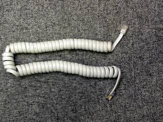
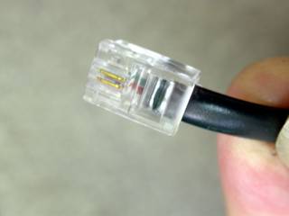
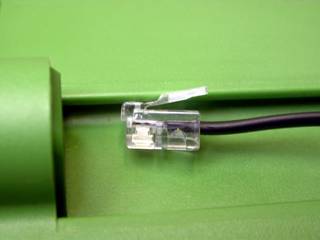
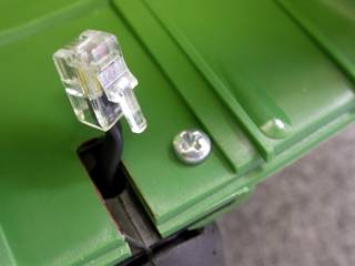
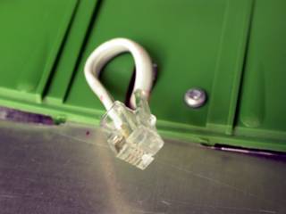
The speaker/battery box cable uses 4 conductors. It is the same as used on lots of modular telephone handsets (RJ-22). These can be found at Radio Shack, Wal-Mart or even your local dollar discount store. This in NOT an RJ-11, the same cable that plugs into the wall, as that one is to wide. It does not need to be very long. A few feet extended will do fine.
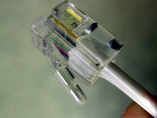
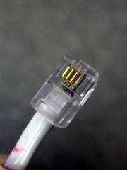
Make sure the cable you buy has 4 wires and is NOT a 2 wire version like the black one above. Just because you see 4 gold pins, does not mean there are 4 wires inside, look closely before you buy. Also the width of some of the connectors vary. You might want to take the battery box with you to check for a correct fit.
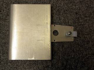
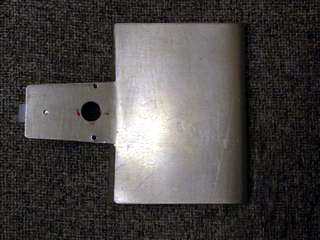
3. Constructing the hip mount bracket
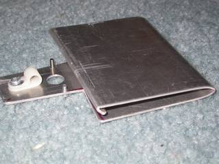
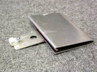
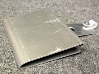
This bracket is one piece and is made out of aluminum. The bracket can be as wide or narrow as you would like. The depth of the bend and its height, depends on the belt you are going to use. I chose this width for comfort and stability of the control head. The nose piece has the same dimensions as the triangular piece on the original shaft, the part that holds the control head on the shaft. I might refer to this as the "slide" part of the bracket. The large hole is for the new Battery/Speaker box cable. The two smaller holes on either side of it is for the mounting screw inside the housing. They are tapped to 4-40. You only need one, but I added two incase you wanted to turn the bracket around on your belt. That will be a matter of preference and comfort. I added one other tapped hole near the end for mounting a strain relief loop. The small extra bend in the belt part near the nose (slide) is not really necessary. I will provide construction dimensions soon if needed. But you should be able to make this from these pictures and measurements taken from to original mounting slide mount on the shaft.
Measurements for the nose part (or slide) of the bracket .
1.135" at the narrow end. 1.330" at the wide end.
Overall length is 1.870" You may have to "file to fit" for your particular housing.
The cable hole is around .413" or drill index number "Z" You could use up to a .500 or 1/2" drill. But no more as you might weaken the bracket.
The holes for mounting the bracket to the shaft's slide are drilled and tapped to 4-40.
The same for the strain relief mounting hole. Remember the screws must be just long enough to engage the threads in the bracket
and NOT protrude thru. Otherwise the housing will not slide onto the bracket correctly.
The belt attachment part of my bracket is 4" wide and 3" deep.
4. Disassembling unit.
Make sure you have removed the batteries from the unit !!
DO NOT do these modifications if your work area is prone to static shocks!!
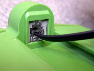
Remove the coil and all the lower shaft assembly. Side off the battery/speaker box. Disconnect the cable connecting it to the main assembly. This is done just like a phone jack cable, by pressing down on the tab at the top.

You now must remove the 3 Philips head screws. Next remove the connector retaining nut and washers. This is best done using a socket. Pliers will just make a mess.
Be careful as the control head will now separate. But be careful not to let it go to far as you might damage the power /sound cable connector inside.
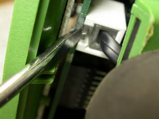
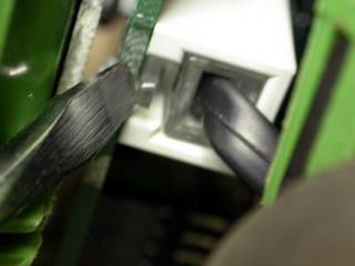
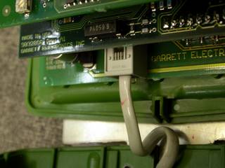
With the housing and control panel barely separated, use a small screw driver to un-lock the cable leading from the shaft to the electronics. This is the same type connector used on the battery box. Just push down the small tap at the top, releasing the cable.
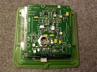
After removing the control head electronics, put them aside for use later. DO NOT adjust, or move anything on the panel. It is very fragile and can be damaged easily. Once again, beware of static electricity! It can destroy electronics. DO NOT do these modifications if your work area is prone to static shocks, like while walking on carpet and then touching something metal.
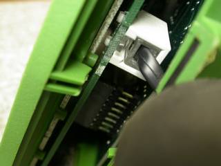
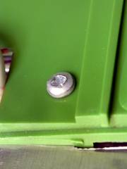
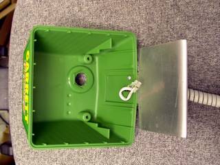
Inside the housing you will see and small screw next to the cable. Remove it and place it aside. It has special threads and is made for plastic. It will not be used for re-assembly. But keep it in a safe place incase you wish to return the unit to its factory configuration.
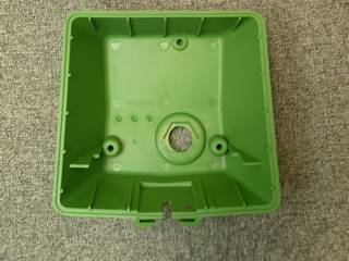
Now push the housing forward away from the cable, it should just slide off. Place it aside for use later. DO NOT attempt to remove the existing cable! Just leave it in place. The 3rd picture is of the shaft re-assembled and the cable from the coil coming up from the bottom. I later covered this end of the old modular cable with heat shrink for protection. You can use electrical tape if needed.
If you have not yet built you belt bracket, now would be a good time to get the measurements for the nose piece area. It will be the same as the slide you just removed the housing from.
5. Reassembling the unit with the modifications.
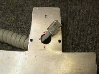
Put one end of the new battery/speaker box cable thru the hole in the bracket. Slide the bracket into the slot on the housing. Now secure the bracket to the housing using a new 4-40 screw. Make sure this screw is only long enough to go from the inside of the housing, thru it and thread ONLY into the bracket without coming out the other side. If it does, it will damage the housing. You only need about 2" of cable passing into the housing.
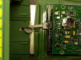
Now retrieve the control panel assembly. Carefully plug in the new cable to the control panel. You can wait to insert the mounting screw until you have connected the control panel. Then pull the access back thru to the outside of the housing. Re-assemble the unit, being careful NOT to pinch the new cable. Don't forget the mounting screw!
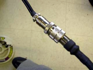
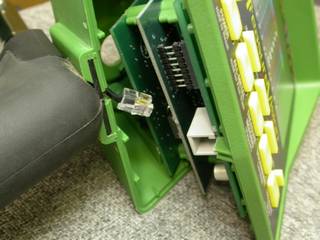
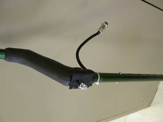
Replace the connector nut and washers along with the 3 Philip's head screws. Remember to use a socket on the housings cable connector. Use a socket ONLY, or a socket attached to a drive handle, no ratchet should be required or you might strip it out. Or worse, you could damage the connector! The second picture above is the new extension coil cable connected to the actual cable going to the search coil.
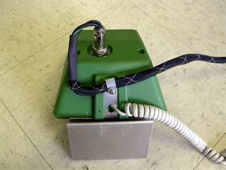
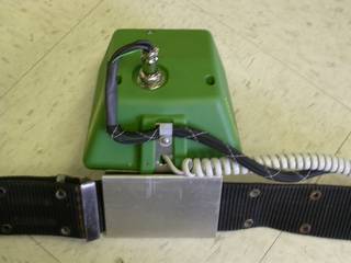
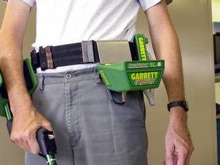
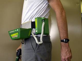
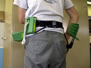
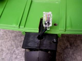
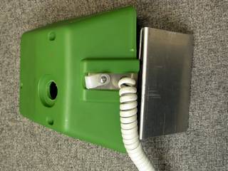
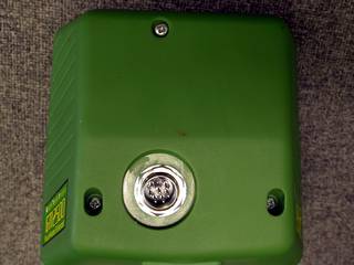
Here are some pictures of the assembled unit showing the new battery/speaker box cable exiting the assembly. You can also see the new coil extension cable attached and going thru the strain relief loop. Now plug the new cable back into the battery/speaker box. I tie wrapped the extension cable to my web belt and fed it around the rear as seen in the pictures at the top of this web page.
If you have any questions or suggestions for this page.......
SEND E-MAIL to mking11@earthlink.net